Recently, I acquired an assortment of 1% tolerance resistors which replaced the previous 5% tolerance resistors. I did not expect too much of a change from this, yet I was curious to see if there would be any visual improvement on the oscilloscope. Long story short, the resistors helped balance the positive and negative supply rail values from the dual power supply circuit. Other than that, most things appeared as it did before.
Previously, I used a polystyrene capacitor for the astable multivibrator.
In an effort to achieve a more accurate result, I switched to a ceramic capacitor of 100[nF]. This change, in addition to lowering the voltage from ±9[V] to ±5[V], successfully achieved a cleaner square wave output.
Also, I had connected the ground wire of my oscilloscope to the common node of the complete circuit. This resulted in a significant offset voltage for the square wave. I disconnected the probe's ground wire and discovered that the unwanted offset was nearly eliminated! This particular action was really a shot in the dark that just so happened to turn out right. Hurray for surprise progress!
Yes, yes...this is all quite boring if no pictures are shown... Here ya go! ;)
Before (connected to the dual power supply circuit)...
A comparison:
1. The square waves are much more square! Compare the vertical scale of the grid in the first screenshot at 3.50[V] and that of the second screenshot at 1.00[V]. Although, it is worth pointing out that the first screenshot was captured during a supply of ±9[V] and the second at ±5[V].
2. The mean of the second screenshot shows a beautiful 0.00[mV]. In reality, it was flipping back and forth from -40.00[mV] to 0.00[V], yet it's close enough for me.
3. The difference between Vmin and Vmax is much less in the second screenshot than the first. Compare the difference of 1.26[V] in the first screenshot to the difference of 0.4[V] in the second screenshot.
4. The frequency is also different because of different component values.
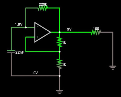
The circuit ultimately changed from this...
To this!
*Please disregard the voltage shown on the inverted input of the op-amp; it is a value that changes with respect to time (and a screenshot is a snapshot of time). Please, do not think that the voltage value is constant. In hindsight, it would've been better to leave those values out of the shot.
In the Falstad circuit screenshots, you may observe a few changes. The most notable change is a potentiometer (10[kOhm]) which replaced the two 100[kOhm] resistors in the first circuit screenshot. This potentiometer allows me to change the frequency of the square wave without having to constantly replace the capacitor and "feedback" resistor (I put "feedback" in quotation marks because the op-amp does NOT have negative feedback).
You may play around with the updated circuit here.
Overall, my new Verdict for this circuit is...
91% pleased=Very Pleased! Grade: A
From here, I believe I am ready to move on in building a waveform generator! :) The generator should be able to create square, triangular, and sine waves of varying frequencies...we'll see what happens!
As always, please feel free to share your feedback. I am always willing to learn and improve myself when possible!
Stay positive!


No comments:
Post a Comment