Objective: To create a functional waveform generator that produces square, triangular, and sine waves.
Application: A waveform generator has several uses ranging from setting a timing sequence to finding the response of a circuit. It is an important and common piece of lab equipment in an electronics lab. I read somewhere that someone just used Audacity and an old MP3 player to generate the different waveforms...ingenious!
Why: Instead of spending more money on a waveform generator, I decided to build one! Granted, it may not be perfect (so far, none of my projects have been perfect), but I believe it will get the job done much cheaper!
Simulation
Now, I know I've been using Falstad up to this point, but for this project I used LTSpice. LTSpice is an official SPICE simulator for circuits and electronics (AND it's free! :D). Although Falstad is great for visualizing common and simple circuit configurations, a real SPICE simulator is desired when wanting to dive deeper into more complex circuits. Plus, Falstad gets a bit laggy on those larger circuits, and I like to pinpoint certain time intervals when scoping circuit characteristics (which cannot be done on Falstad as far as I know). Unfortunately, LTSpice isn't as cool looking as Falstad's circuit simulator (bummer).
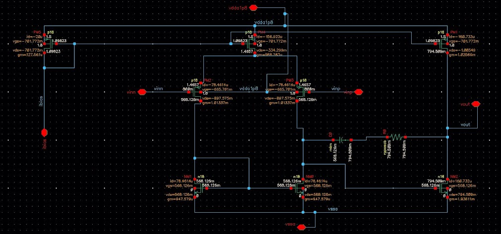
Here is the circuit for the waveform generator in LTSpice!
 |
| Figure 1: LTSpice circuit for waveform generator |
Essentially, I was following the diagram below:
 |
| Figure 2: Waveform generator circuit diagram from www.circuitstoday.com |
Looking at Figure 1 (or even better Figure 2), you may observe that I am still using an astable multivibrator which creates the square waves. By connecting the output of the astable multivibrator to an op-amp integrator, we create triangular waves. We repeat this process with the output of the triangular wave generator to create sine waves. It's Calculus!
Using the magic ".tran 0 0.11 0.1 0.0001" LTSpice simulator parameters (I have no idea...I just used an interface to set the parameters, and that popped out of nowhere...), we achieve the following simulated results:
 |
| Figure 3: Simulated waveforms for circuit shown in Figure 1 |
Satisfied with our simulation results, we move on to the build.
Build
There is a bit going on with this project here. In fact, this project implements all of my previous work! So here unfolds the strategy:
1. Set the power supply box to 11.00[V]. Why 11[V]? Well, for fun, I liked hooking up a speaker to the output to see (and hear) what would happen. This action would cause a significant increase in current (4[Ohm] speaker in series with a 100[Ohm] resistor connected across the output and gnd; a crude setup). Thus, I decided to lower my voltage from 18[V] to 11[V] which reduced the current throughout the circuit (probably not necessary).
2. Connect my single-to-dual power supply circuit to the supply box. I now have ±5.5[V] and a common node for my waveform generator.
3. Next, connect my astable multivibrator circuit to create the square waves. So far, all of this has been done before, and is recorded in my last post from Aug. 15, 2017.
4. Connect an op-amp integrator to the output of the astable multivibrator. This should produce triangular waves in the output of the second op-amp.
5. Connect another op-amp integrator, yet this time at the output of the second op-amp (the one producing triangular waves). This should produce sine waves in the output of the third op-amp.
As always, I like to provide a poor quality shot of my build!
 |
| Figure 4: Waveform generator physical build on breadboard |
For those of you who don't want to fall down that rabbit hole, I have provided you the following schematic from LTSpice:
 |
| Figure 5: LTSpice waveform diagram w/o component values |
Through testing, component values did change. I encountered clipping with the triangular waves (clipping on the bottom). I discovered a huge reduction in peak-to-peak voltage. I found out that my sine waves just really wanted to be triangular waves too! All of these issues encountered from testing, led me to make some necessary changes to some of the component's values. In turn, I learned a lot about analog circuit behavior!
The following values apply to the final waveform generator circuit:
C1=100[nF]
R1=10[kOhm]
R4/R5=10[kOhm] potentiometer
R2=100[kOhm]
R3=100[kOhm]
R6=200[kOhm]
C2=300[nF]
R7=200[kOhm]
C3=100[nF]
Results
We will go down the list! The square wave...
 |
| Figure 6: Square wave generator results |
The triangular wave...
 |
| Figure 7: Triangular wave generator results |
Notice the reduction in Vpp? The sine wave...
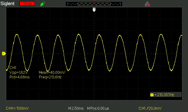 |
| Figure 8: Sine wave generator results |
Once again, we see a reduction in Vpp though not as drastic.
The Reaction
These are fantastic!...which is to be expected since I did spend the time in testing to make sure I achieved a good result.
The Rundown
There are a few very minor issues, but just minor. I would prefer the triangular waves to be more linear. The rises and falls barely appear concave much like the peaks and valleys of the square waves...not a huge issue at all, but noticeable.
All means are very low with the largest coming from the sine wave at 40[mV]. Awesome!
Frequencies are consistent, and do change accordingly when turning the potentiometer.
The Verdict
95% pleased=VERY PLEASED! Grade: A
Through much testing, much is achieved in the electronic world, and I believe this project is proof of that! :)
End
I've been anticipating this waveform generator project for a while. Now that I'm finished, I'm wondering what I will do next! I'm thinking something along the lines of voltage regulator, but we shall see!
As always, I do not expect everyone to read every word...sometimes I'm not even sure I have an audience! :O Yet, if you leave learning something, then I consider that an accomplishment! ;)
Speaking of which, maybe you have a better idea of how I should do things...if so, please let me know. I'm always willing to improve!
Stay positive! -Kaylon


No comments:
Post a Comment